This part of the disassembly process is the most difficult. The main board is connected via screws, a USB connector, and a circuit connector hidden under the board. In addition, there are wires at the lower end of the board that connect to the speakers and components under the board. You do not have to remove these to get under the board if you simply flip the circuit board over onto its top when it is removed. 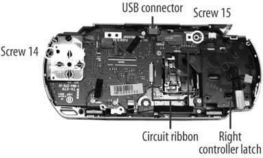
-
Unlatch the right controller circuit strip and the UMD drive circuit strip.
-
The controller lifts from the bottom, and the UMD catch requires slight pressure from the left against the black plastic arms.
-
Remove screw 14 from the top right of the circuit board.
-
Remove screw 15 from the left side of the left controller.
-
On the top right of the main circuit board, carefully remove the power connector (white with black wires). This will require you lift the board first before disconnecting the white plastic socket.
-
On the lower side of the left controller, pry up the circuit board over the catch and lift the controller over the top of the PSP.
-
Peel back the tape holding the black power wire and lift the antenna off the main circuit strip, disentangling it from the tape and the right controller.
-
Slowly lift the circuit board up off the PSP by slipping out the USB connector from the top plastic shell, then raising the top of the board and flipping it over the bottom of the PSP. You will need to apply pressure and pry the board off a hidden connector that keeps the board connected to components deeper inside the PSP.
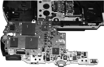
Chip 1
-
CXD2962GG
©2004SCEI
507D10E
641711
Chip 2
-
CSD1876
©2004SCEI-102GG
504A99E
278491
Chip 3
-
SAMSUNG 501
K5E565H8CM-D060
Chip 4
-
SC901583EP
MXAEA0423
Chip 5
-
MB44C001
0505 M51

No comments:
Post a Comment